

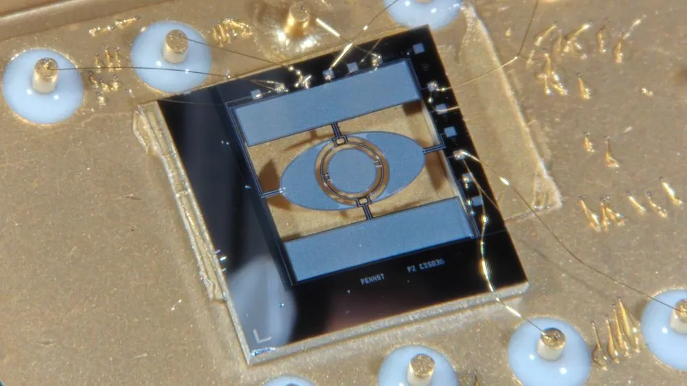
A research team at Pennsylvania State University has developed a tiny mirror that can sweep laser light left-right and up-down while also changing its own surface shape to adjust the focal distance.
The findings were published in the peer-reviewed journal Microsystems & Nanoengineering on July 17, 2026, and the university announced the work on August 27. The chip measures 5.5 mm on each side. It combines beam scanning and focus adjustment—functions that have often required separate optical components—into a single MEMS (micro-electromechanical system) device.
Hearing that "light can now be moved in three dimensions" might suggest that this small mirror alone can capture 3D images. That is not quite what happened.
What the device actually controls are the position where the laser strikes and the distance at which it comes into focus. Tilting the mirror changes the beam's position on a plane, while changing the curvature of the mirror surface adjusts the focus along the depth direction.
What the paper demonstrates is the behavior of the prototype chip itself and a proof-of-concept test using a simple microscope with a standard resolution test chart. It does not demonstrate imaging of a living brain or the display of AR video.
Steering and focusing light with a single mirror
This micromirror is supported by a double gimbal structure.
Tilting the outer and inner frames separately moves the reflected laser beam horizontally and vertically. In addition, applying voltage to actuators built into the mirror surface can flatten the mirror or slightly curve it.
Changing the curvature of the mirror surface shifts the point where the reflected light converges. This means the device can adjust not just the direction of the light but also the distance at which it comes into focus.
The team achieved these three types of motion using a thin aluminum nitride film, relying on the piezoelectric effect, in which the material deforms when voltage is applied.
The idea of controlling both direction and focus with a single mirror is not new in itself. The paper compares its performance against existing micromirrors that can vary both tilt and curvature.
The authors' comparison went beyond mirror diameter and achievable tilt angle—it also evaluated how fast the mirror can move in both the lateral and depth directions.
For that reason, it would be inaccurate to describe this result as "the world's fastest 3D microscope has been completed." What is being compared is strictly the performance of the micromirror as an optical component.
The advantage of combining everything into one device is that it reduces the need to place separate mirrors for scanning and separate components for focus adjustment.
However, the 5.5 mm square figure refers to the size of the chip itself, not the entire optical system.
In the experiment where the laser scanning pattern was recorded, the team used a 75 mm lens to direct light onto the mirror and a 100 mm lens to shape the reflected light. The microscope experiment incorporated even more lenses and a detector.
The components that can be miniaturized and the optical parts that are still required need to be considered separately.
A fast-moving mirror doesn't guarantee equally fast image capture
When the prototype chip was measured in air, its horizontal and vertical tilt motions showed the largest oscillation near resonant frequencies of 10.05 kHz and 12.29 kHz, respectively.
For the motion that changes the mirror's curvature, a resonant frequency of 141.3 kHz was measured.
In a separate test that measured changes in focal position based on the intensity of reflected light passing through a pinhole, the optical state took 5 microseconds to change in one direction after switching the voltage, and 20 microseconds to return in the other direction.
However, all of these figures describe the motion of the mirror itself.
They do not represent the frame rate—that is, how many completed images can be captured per second.
The team also measured how far the laser beam could be swept in terms of angle. The maximum optical scan angle was 16 degrees.
However, this figure was obtained in an environment evacuated to 0.1 Pa, with each axis driven at resonance. The resonant frequencies mentioned earlier, by contrast, were measured in air. Figures measured under different conditions cannot be combined as if they represent performance achieved simultaneously under a single operating condition.
There was also a difference in the response time for shifting focal position: 5 microseconds versus 20 microseconds.
The authors explain that this is consistent with the time-dependent nature of the piezoelectric thin film's deformation. This means one cannot assume the mirror moves at the same speed when focusing nearer versus farther.
Furthermore, the response speed for a single voltage switch and the frequency achieved when the mirror is driven continuously at resonance are two separate measurements.
Even if the mirror itself can move quickly, that does not guarantee that high-resolution images can be produced at the same speed.
The "Lissajous scanning" method used here moves the horizontal and vertical axes at different periods, tracing out the laser beam across the field of view. As a result, it takes a certain amount of time for the light to pass over the required area with sufficient density.
The finer the scan lines and the higher the image density, the longer it takes to complete a single image.
Therefore, the 141.3 kHz figure reported in the paper cannot simply be reinterpreted as meaning the device can update a 3D image more than 140,000 times per second.
The 63 mm and 5 mm figures came from separate experiments
The research team conducted separate experiments to test how far the focal position could be shifted and to actually capture images using the microscope.
The 63 mm shift in focal position was confirmed in an experiment using the laser's scanning pattern. Meanwhile, in the simplified microscope, the team confirmed that a sharp image of a standard test chart could be reacquired after moving it 5 mm.
| Experiment | What was confirmed | Voltage applied to mirror surface | Scan pattern update rate | Main optical components used |
|---|---|---|---|---|
| Laser scan pattern (Fig. 9 in paper) | Changing the voltage on the mirror surface and moving the screen caused the pattern to come back into sharp focus at a position 63 mm away | 0V to −50V | 1.34 kHz | 75 mm lens on the input side, 100 mm lens on the reflection side, etc. |
| Simple confocal microscope (Fig. 10 in paper) | Changing the voltage and moving a USAF standard test chart 5 mm allowed the image to be reacquired | 0V to 15V | 293 Hz | Three lenses, beam splitter, 100 µm pinhole, photodetector, etc. |
The 63 mm and 5 mm figures are not numbers obtained by racing focal-shift distance under identical conditions.
In the former case, the team examined the position at which the laser's scanning pattern, projected onto a screen, came back into sharp focus. In the latter case, they detected light returning from the test pattern and actually produced an image.
The applied voltage and the optical setup differed between the two experiments.
Therefore, the 63 mm figure does not mean the device can image inside biological tissue to a depth of 63 mm. Likewise, the 5 mm figure does not represent the upper limit of how far this microscope's focus can be shifted.
The field of view in the laser scanning pattern experiment was 5.8 × 2.8 mm, while the field of view for the images captured with the microscope was 1.6 × 1.6 mm.
Being able to scan the laser across a wide area and being able to actually capture an image over a narrower area must be regarded as two separate achievements.
To evaluate practical usefulness, one must consider not only how far the focus can be shifted, but also how wide an area, at what resolution, and at what speed images can be captured.
The microscope in this study used a confocal design.
In confocal microscopy, a pinhole is used to block out light that comes from outside the focal plane. Because changing the mirror's curvature shifts the focal position, the test chart would otherwise appear blurred.
To work around this, the team physically moved the chart and re-captured light at the new focal position to obtain an image.
In other words, this experiment confirmed that changing the mirror's curvature can indeed shift the focal position during actual image capture—not just in theory.
Using the microscope, the team produced a 128 × 128-pixel image from a 1.6 mm square field of view.
The subject imaged was a USAF resolution test chart, and the pattern confirmed was 4 line pairs per millimeter.
What this experiment demonstrates is that the system can refocus optically on targets at different distances and successfully capture an image.
On the other hand, whether the resolution is sufficient to distinguish individual neurons, or whether stable imaging can be maintained while a living subject is in motion, are questions that this study did not verify.
The "small microscope worn by a moving subject" that the university cites as a future application is one candidate use case, not a demonstrated capability.
Improving image quality remains key for wearable microscopes and AR applications
One challenge the research team identified is that the mirror surface does not deform into an ideal circular curve.
The paper confirms that because the deformation of the mirror surface is not perfectly symmetric, "astigmatism" occurs—a mismatch in focal position between two perpendicular directions.
This mismatch interferes with forming sharp, fine-detail images. Correcting it will require either improving fabrication precision so the mirror deforms more symmetrically, or compensating for the effect using surrounding optics.
The performance requirements will also vary depending on the intended future application.
For use in brain observation, researchers would need to test with actual biological samples rather than standard test charts, confirm that sufficient resolution can be achieved, assess how much the illuminating light affects tissue, and verify that stable images can be captured even when there is motion.
For AR applications as well, simply being able to shift focus according to depth is not enough. If lateral scanning speed and resolution are insufficient, the result will not translate into a practical display.
The paper estimates that under ideal conditions for displaying 1280 × 720-pixel images at 60 frames per second, each scanning axis would need to be driven at 40 kHz or higher. The current prototype mirror does not yet reach that requirement.
Combining three types of motion—steering light in two directions plus adjusting focal position—into a single micromirror is a promising design for miniaturizing optical devices.
However, it remains unclear how far the overall system can actually be miniaturized and how stably it can operate once the full setup is assembled—including the lenses and other optical components used in the experiments, the astigmatism issue, and the resolution and speed required for each specific application.
What will matter going forward is not the peak frequency recorded for the mirror alone, but the level of image quality and speed that can actually be achieved once the device is built into a complete microscope or display system.